Wiring diagram and method of diffusion silicon pressure transmitter
Firstly, let's understand the working principle of a diffusion silicon pressure transmitter. It is based on the piezoresistive effect of single crystal silicon and converts the resistance change caused by pressure into an electrical signal output through a Wheatstone bridge. Its wiring mainly depends on the type of output signal and whether the transmitter is built-in. The most common is to have a two-wire 4-20mA output.
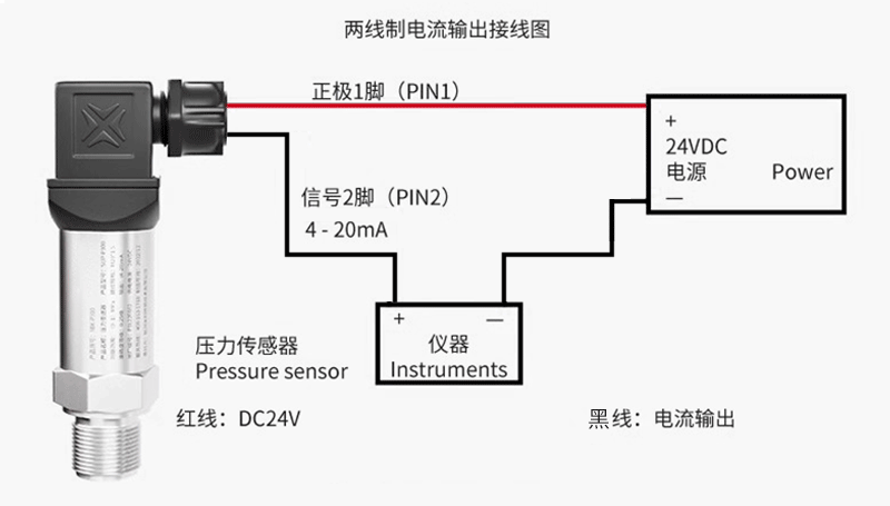
1. Two wire system (4-20mA output)
Wiring analysis: Red wire (or marked with+): connected to the positive pole of the power supply (+24V), black wire (or marked with -): connected to the current input positive terminal of the signal receiving device (such as the AI module of the PLC). Connect the current input negative terminal (or common terminal COM) of the signal receiving device back to the negative terminal (0V) of the power supply.
Working mode: The internal circuit of the transmitter adjusts its impedance to vary the loop current between 4mA (corresponding to zero voltage/range lower limit) and 20mA (corresponding to full range pressure). The power supply supplies power to the entire transmitter through the signal line.
Advantages: Strong anti-interference ability (current signal), simple wiring (only two wires are needed), long-distance transmission, and inherently safe design that is easier to implement.
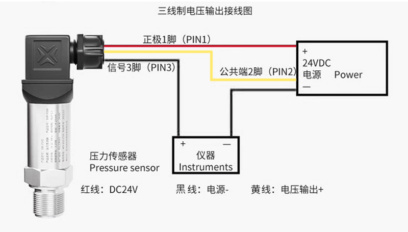
2. Three wire system (voltage output type, such as 0-5V, 0-10V, 1-5V)
Three wires: positive power supply (+Vcc, usually+12V~+24V DC), negative power supply (GND), signal output (Vout+).
Signal Ground: The ground (reference point) of the output signal is usually connected to the power ground (GND) inside the sensor.
Wiring: The red wire (or marked with+V) is connected to the positive pole of the power supply, and the black wire (or marked with GND) is connected to the negative pole of the power supply and the common ground (COM) of the signal receiving equipment. Connect the green/blue/white line (or mark OUT/Sig) to the analog input positive terminal of the signal receiving device (the input negative terminal of the signal receiving device is usually also connected to COM/GND).
Disadvantages: The transmission distance of voltage signals is limited, and they are easily affected by line voltage drop and interference.